Angle Shift in Bandpass Filters
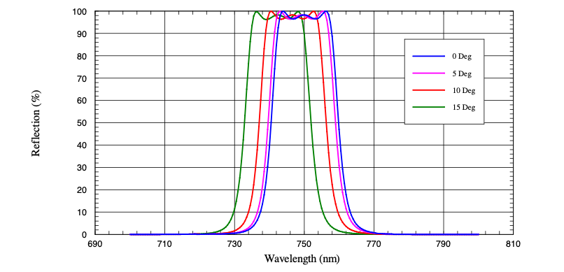
All Optical Interference Bandpass Filters exhibit some degree of shift with the angle of incidence (AOI). Since the layers of a bandpass filter operate in the coherence range of the desired wavelengths, a departure of AOI from zero degrees results in the shortening of the center wavelength. To achieve the desired bandwidth, standard optical bandpass filters are designed with the minimum layer thicknesses needed in the absentee spacer layers. An example is given below (Fig. 1) of a standard bandpass filter centered at 750 nm with a bandwidth of 20 nm. One can see that the filter will still transmit the center wavelength (CWL) to a tilt of 15° AOI. This limits the function of the filter to about f/1.9 or a 30° full cone angle.

Figure 1: Standard 750 nm Bandpass Filter Transmission Over Angle
Fortunately, optical design strategies exist to reduce the angle shift, thereby increasing operating cone angle. These involve increasing the thickness of the absentee layers and consequently the number of cavity elements needed to maintain edge steepness. However, this design is more complex and the deposition process is more difficult to control (and is more costly). Therefore, it is not routinely used in manufacturing, although, it is available as a custom filter option.
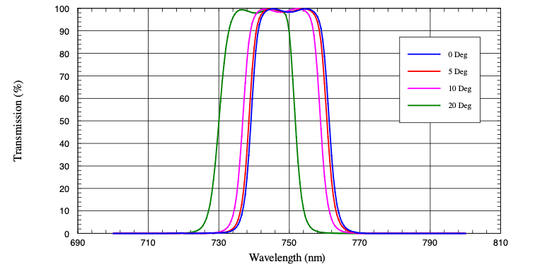
As optical systems become more compact, they tend to use higher index glasses with greater lens curvatures and operate at faster f/#’s. This, in turn, drives the need for bandpass filters with a reduced shift. The transmission over angle of an enhanced, reduced-shift bandpass filter given below (Fig. 2).

Figure 2: Enhanced 750 nm bandpass filter transmission over angle.
The enhanced filter will now operate to an angle of 20° AOI (40° full cone angle). Thereby increasing the operating cone to 40° or f/1.4. This benefits systems that need to collect and process a wider angle of light.
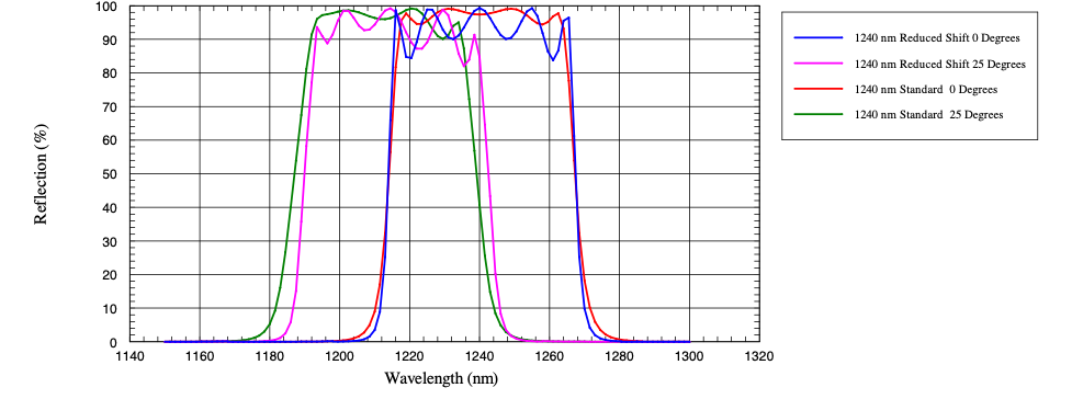
The design strategy described above works well with filters that have an intermediate bandwidth. However, it is more difficult to correct the shift of wide bandwidth filters. An example (Fig. 3) is shown below illustrating the case of a 1240 nm filter with a bandwidth of 50 nm. This width corresponds to about 4 % of the center wavelength whereas the previous 750 nm example has a width of 2.6%. If the 750 nm design were to be shifted to 1240 nm the resulting width of 36 nm would be representative of an intermediate bandwidth.
 Figure 3: Standard and Enhanced 1240 nm bandpass filter transmission over angle.
A wider filter design requires thicker absentee layers to reduce the ripple in the pass band. The result is a standard filter that performs much like a reduced angle shift filter. A comparison is given in Figure 3. Both a standard and a reduce angle shift design show very similar shift to 25° AOI. Therefore, the wider the filter, the angle shift reduction is much less effective.
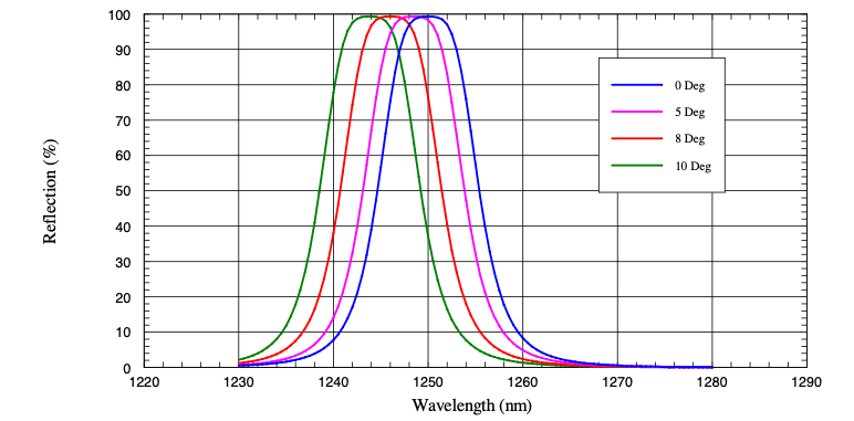
On the other end of the bandwidth spectrum, very narrow filters prove to be more difficult in reducing the shift with angle. Below is an example of a 1250 nm filter with a width of 10 nm or 0.8%.

Figure 4: Standard 1250 nm bandpass filter transmission over angle.
Here we can see that the center wavelength transmits to about 8° AOI. A reduced shift version of this filter would see transmission out to 10° AOI. This may not seem to be much but proportionally it is very similar to the 750 nm bandpass filter shown in Figure 1.
While it is limited in its effectiveness, especially for filters wider than about 3 % bandwidth and very narrow filters less than 1% bandwidth, it can still be concluded that angle shift reduction is possible with the right design.
Whether you are looking for assistance with angle shift, beam deviation, polarization or any other aspect of your optical design, Andover Corporation engineers are always available to answer any technical questions you might have and to offer custom optical filter manufacturing or off-the-shelf optical solutions.
